|
|
Simple Steps for the Removal and Inspection of Front Wheel Driveaxles and C.V. Joints |
 FWD Parts  C.V. Boots  Rear Line Shaft  Technical Products  Business Opportunities  Directory of Experts  On-Line Reply  Order Form  RCV Home Page |
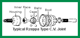 The following procedures are recommended for the removal and inspection of most front wheel drive C.V. joints. These sample steps are for general information purposes only and do not apply for all cars. Make sure you observe good safety practices from the time the car goes on the lift until the job is finished. | ||
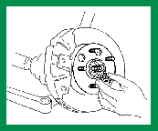 1. Loosen lug nuts and wheel spindle nut. Lift and block vehicle. Remove wheel nuts and wheel. Then remove the wheel spindle nut. |
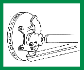 2. Remove the nut holding the lower ball joint to the hub assembly. NOTE: On the McPhearson strut-equipped cars, it is not necessary to remove brake caliper or disconnect tie rod or strut assembly. |
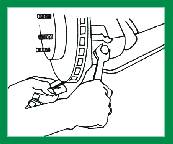 3. Some applications have a transverse bolt that retains the ball joint stud to the hub assembly. This should be removed. | |
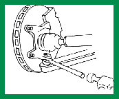 4. Loosen the ball joint stud from the hub assembly with a fork, being careful not to damage the flexible seal that protects the ball joint. |
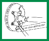 5. Using the leverage of a pry bar, completely separate the lower ball joint stud from the hub assembly. Push the hub assembly to one side of the lower control arm. |
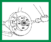 6. Free the C.V. Joint from the hub assembly by tapping the spindle. Be careful not to damage the spindle threads. | |
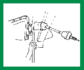 7. Using the leverage of a pry bar, separate the drive shaft from the transmission. On some models, the drive shaft is bolted to the transmission and these bolts must be removed. |
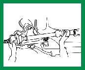 8. Support both ends of the drive shaft when removing it from the vehicle. |
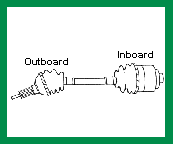 9. All front wheel drive shafts have (2) C.V. Joints, an outboard and inboard. Each joint is lubricated with special high temperature grease, and protected with a C.V. boot seal. | |
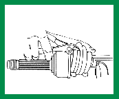 10. Clamp drive shaft in a soft jawed vice. Cut boot clamps at each end of boot with side cutters. Cut the boot lengthwise and discard. |
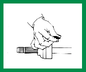 11. Rub grease from the C.V. Joint between your finger and thumb. If the grease feels gritty you can assume there has been damage. |
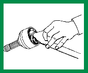 12. Wipe away all grease from the face of the joint and determine how the joint is retained on the shaft. (Incidentally, you should remove grease whenever you find it throughout your inspection to allow a more careful analysis of the unit). | |
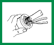 13. C.V. Joints are held in position on the drive shaft by two different methods. GM, early Fords, and Volkswagen Joints can be released by expanding a front facing snap ring and sliding C.V. housing off shaft. |
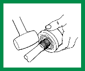 14. Chrysler, AMC, and most imported joints are held into position on the shaft with an internal snap ring. These housings can be removed by striking the joint face with a mallet. |
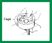 15. Place joint face up in a vice. Press downward on one side of the inner race to tilt the bearing cage high enough to remove a ball from the opposite side. If joint is tight use a mallet and brass drift to tap inner race. Repeat this step until all six balls are removed. | |
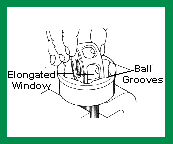 16. Tilt the cage assembly vertically and position two opposing windows in the area between ball grooves. Most cages have elongated windows specifically for this purpose. Remove cage and inner race assembly by pulling them upward from the housing. |
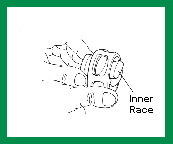 17. Rotate inner ball race 90 degrees to the cage and align one of the race spherical lands with an elongated cage window. Raise and remove inner race by swinging outward. Now clean all components thoroughly. |
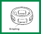 18. Check the cage fro cracks or dimpling. This dimpling, as illustrated above, allows for excess ball movement which is the source of a clicking sound during turns. | |
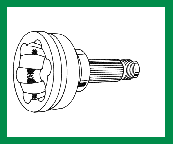 19. All outboard housings and inner races show contact wear in the area where the ball moves back and forth in the groove. This wear is normal and advances as mileage on the joint increases. These parts should not be discarded, however, until the wear pattern becomes extreme. |
|||